DataLogger SETIER ENERGY V0.0 Hardware EN
Attention
We invite you to refer to this document to assemble Datalogger SETIER V0.00 FLOWMETER Hardware Part.
Attention
SETIER is a participative project open to all, it requires skills in electronics and to respect the safety rules. SETIER must be assembled in a professional context and by people competent in electronics. The SETIER team cannot be held responsible for any material or human damage which would be associated with the use or the assembly of Datalogger SETIER. The SETIER team cannot be held responsible if the equipment does not work after assembly. You may redistribute and modify this documentation and make products using it under the terms of the CERN-OHL-P v2 (https:/cern.ch/cern-ohl). This documentation is distributed WITHOUT ANY EXPRESS OR IMPLIED WARRANTY, INCLUDING OF MERCHANTABILITY, SATISFACTORY QUALITY AND FITNESS FOR A PARTICULAR PURPOSE. Please see the CERN-OHL-P v2 for applicable conditions.
Technical date
Parameter |
Specifications |
Units |
Input voltage (VCC) |
3.3 to 5.5 |
V |
Effective measurement range |
0 to 5, 10 or 20 |
A |
Measurement accuracy |
+/-1% |
% |
Non-linearity |
+/-0.2 |
% |
Cable lenght |
1 |
m |
Operation temperature |
-25 to 70 |
°C |
Opening size (Lxl) |
13x13 |
mm |
Data storage |
µ SD card |
Assembly of the datalogger
Step 1 : Electronic board assembly
The first part consists of assembling the different electronic board together.
Material List
Name |
How Many |
Picture |
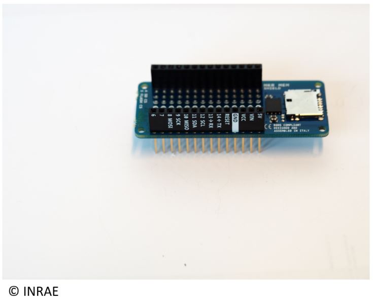
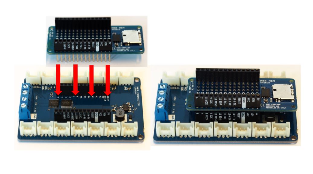
MKR MEM SHIELD |
1 |
|
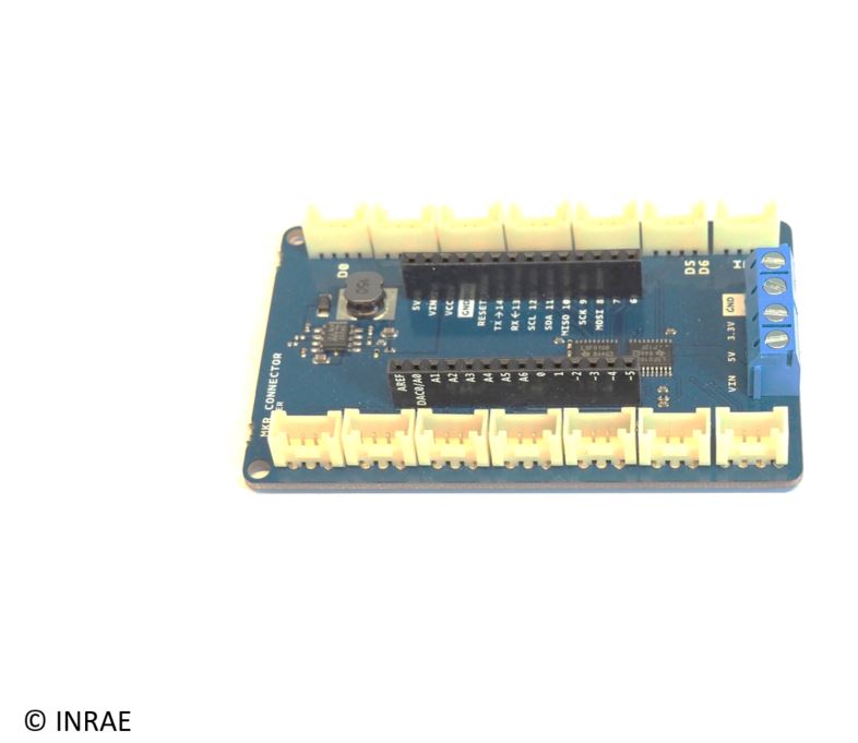
MKR Connector Carrier |
1 |
|
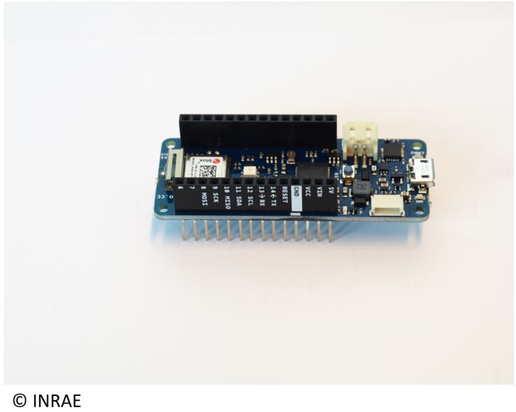
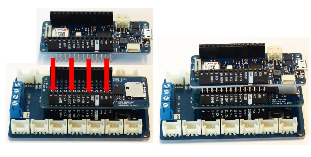
MKR WIFI 1010 |
1 |
|
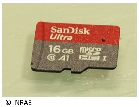
µ SD card |
1 |
|
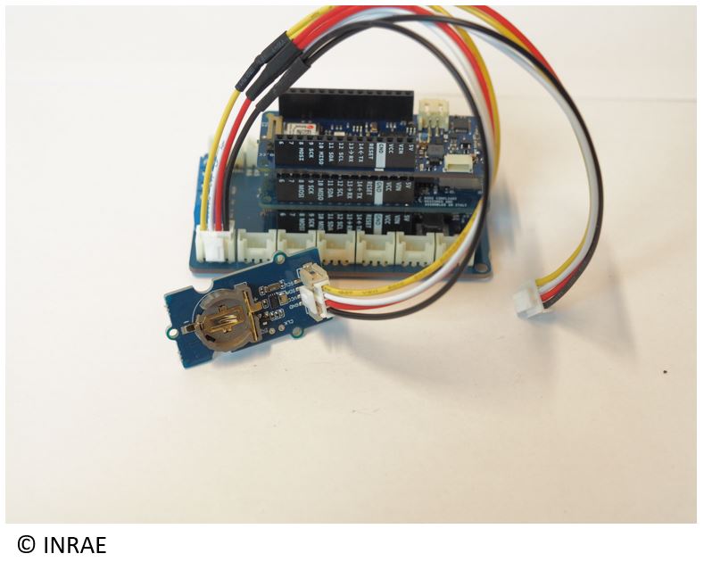
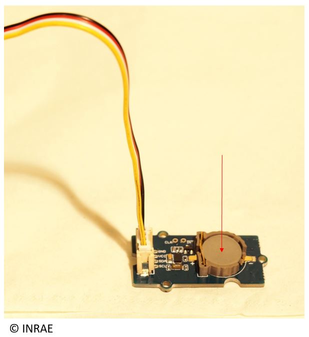
RTC module |
1 |
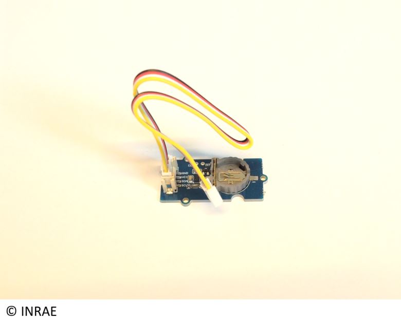
|
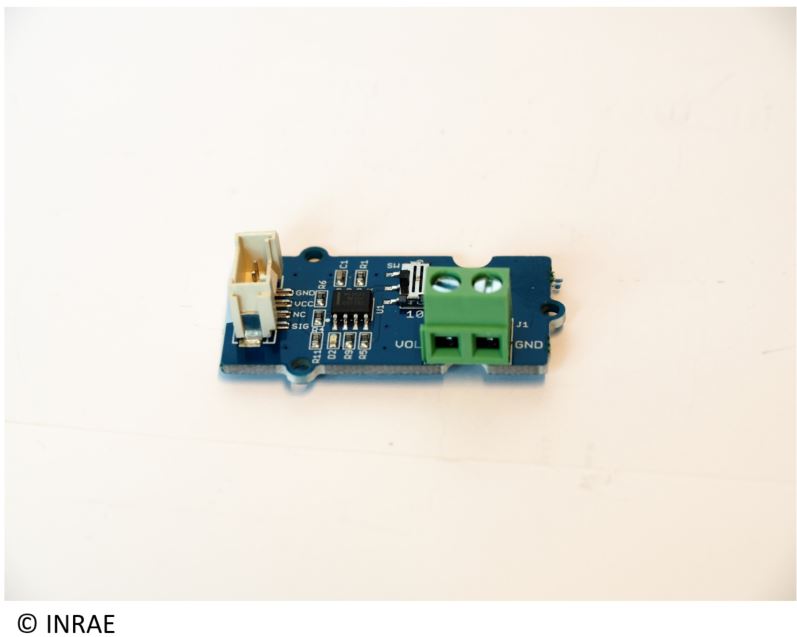
Voltage divider board |
1 |
|
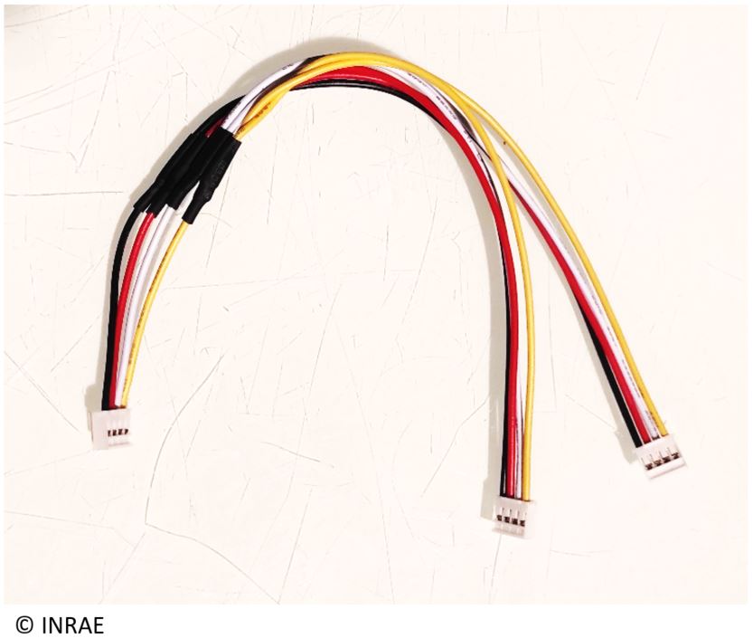
Double wire grove |
1 |
|
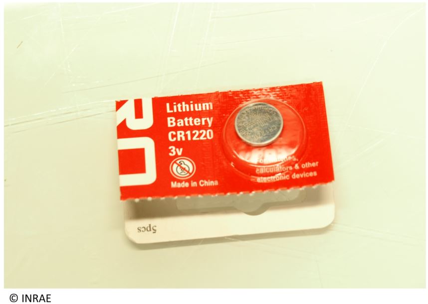
CR1220 lithium battery |
1 |
|
Connect the MKR MEM Shield on the MKR Connector Carrier.
Connect the MKR WIFI 1010 on the MKR MEM Shield.
Insert the µSD card inside the MKR MEM SHIELD.

Connect the simple part of the double wire Grove sur le port TWI de la carte ARDUINO CONNECTOR CARRIER.

Take the RTC module and connect on of doble wire extremity on it. The other side will be connected later.
Take the CR1220 lithium battery and insert it on the RTC module.
Take the voltage divider board and plug its wire on.

Connect the other side of the wire from the voltage divider board to the A5-A6 of the MKR CONNECTOR CARRIER.

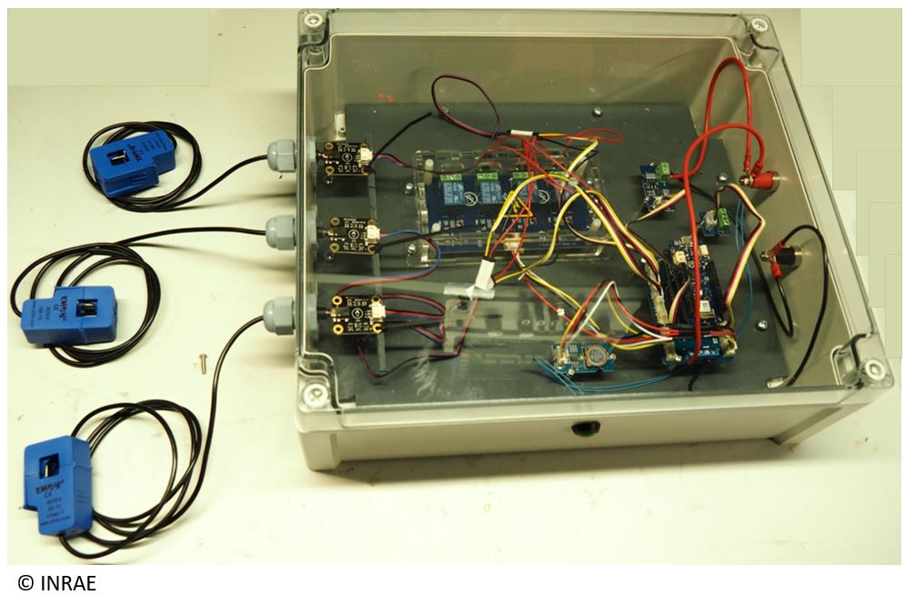
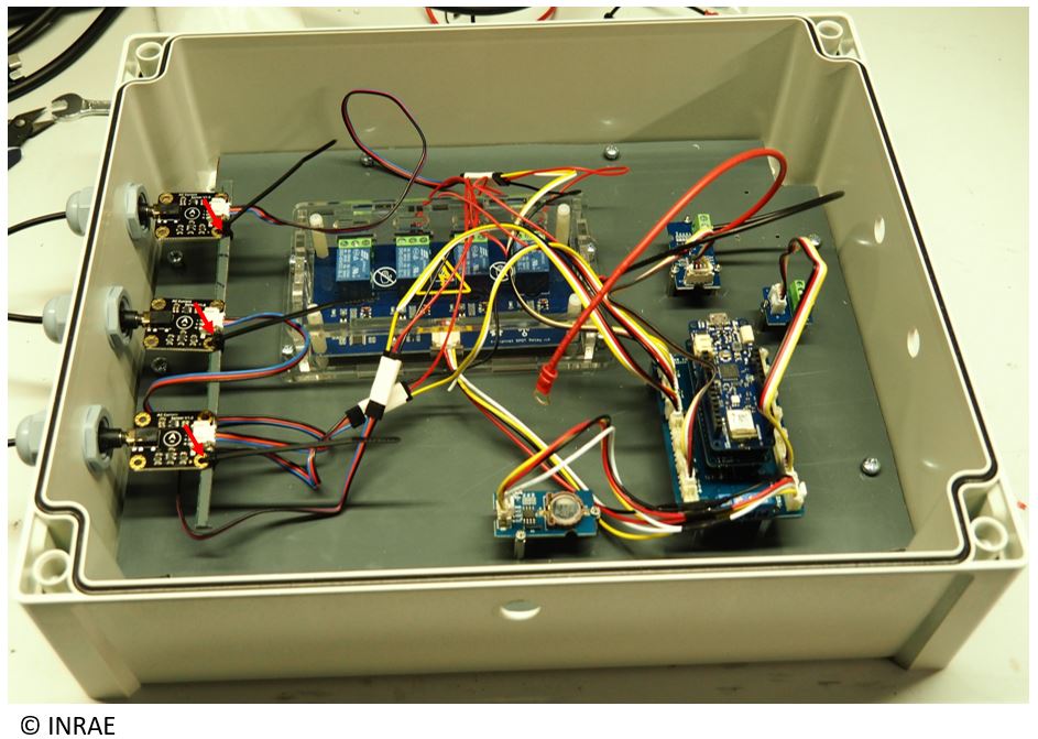
Step 2 : Mechanical assembly
That second step consist of assembling the of the different part of the datalogger, and to fix it inside a box.
Material list
Name |
How many |
Picture |
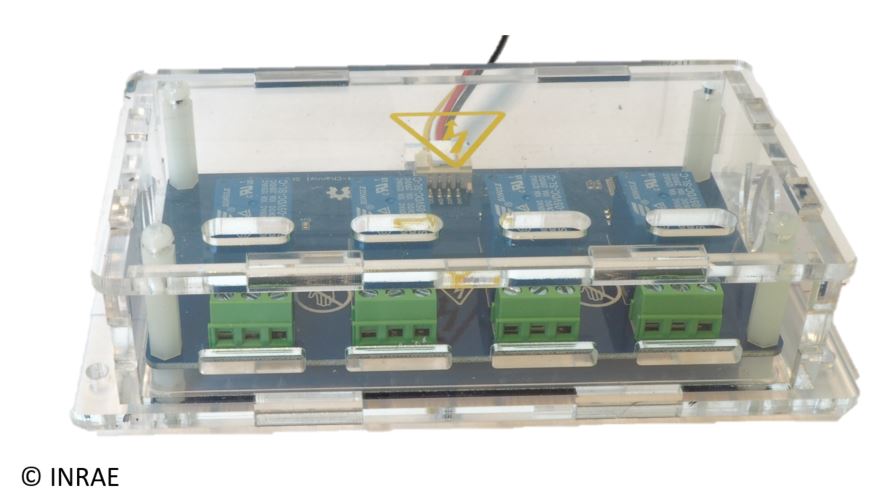
4 relay board |
2 |
|
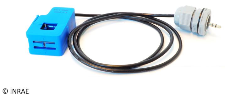
Current clamp SEN0211 (20A Sensor) |
1 |
|
Current clamp SEN0288 (10A Sensor) |
1 |
|
Current clamp SEN0287 (5A Sensor) |
1 |
|
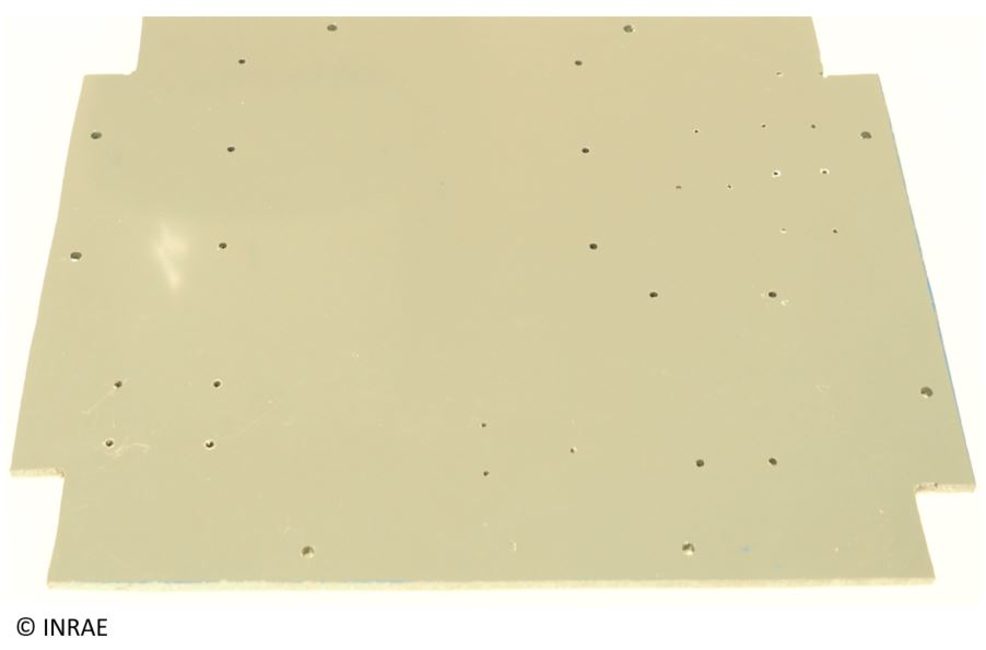
PVC plate |
1 |
|
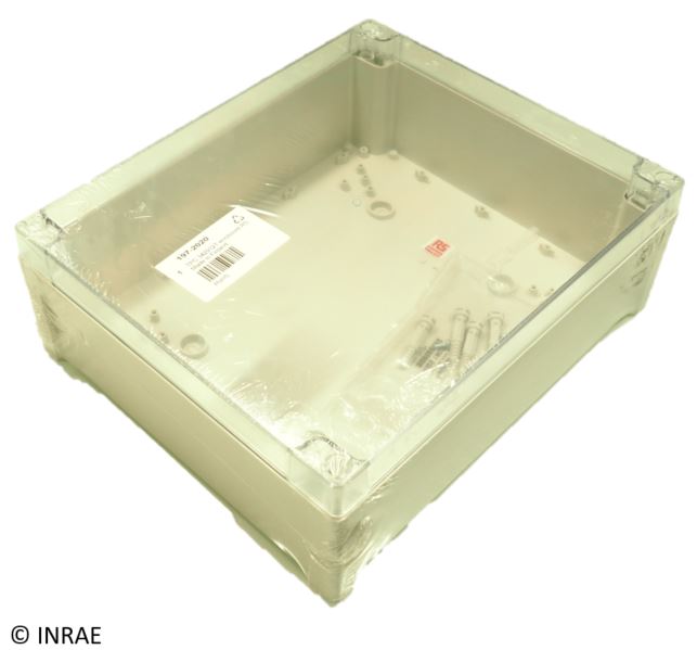
Box 344 x 289 x 117mm |
1 |
|
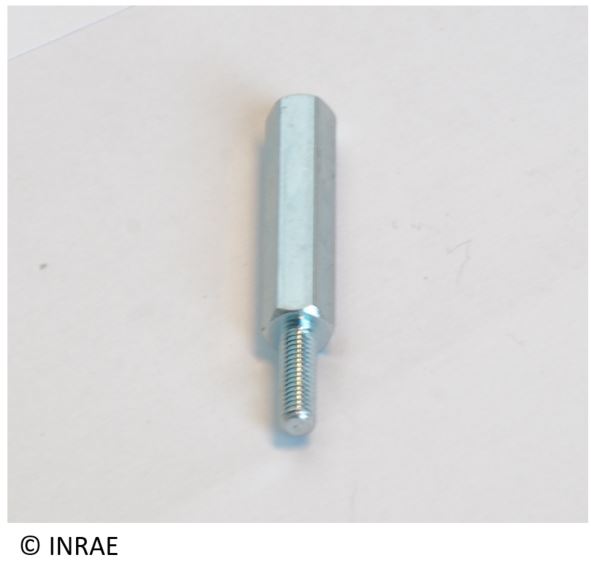
Spacer (M2 and M3) 20 mm long |
+/-10 of each |
|
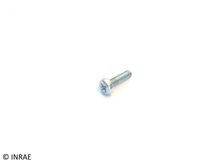
Screw (M2 and M3) |
+/-10 of each |
|
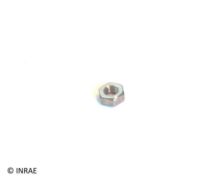
Nuts (M2 and M3) |
+/-10 of each |
|
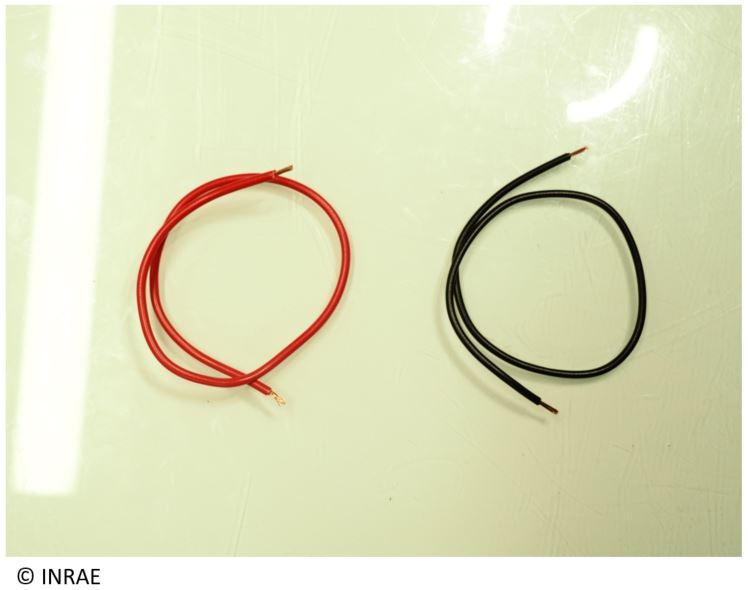
12 cm red/black multi-strand cable diameter 1,6 mm |
1 of each color |
|
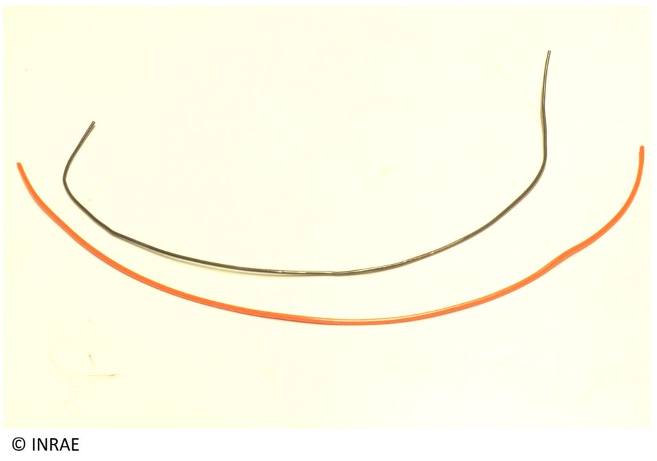
12 cm red/black multi-strand cable diameter 3 mm |
1 of each color |
|
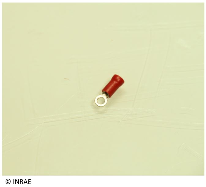
Crimp lug |
2 |
|
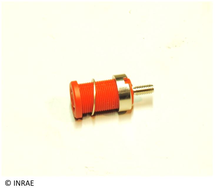
Red banana plug (external diameter 12 mm) |
1 |
|
Black banana plug (external diameter 12 mm) |
1 |
|
cable gland (external diameter 18 mm) |
3 |
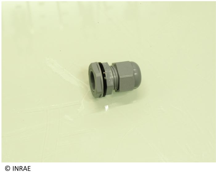
|
Grove/Picot wire |
3 |
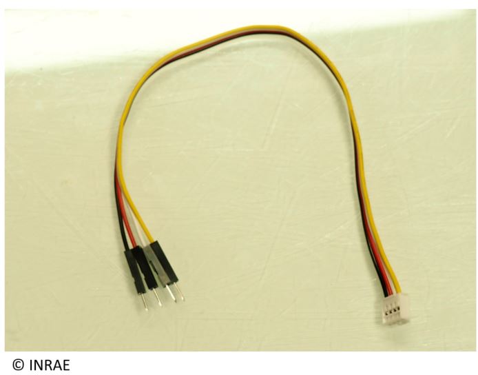
|
Picot/Picot wire(red and black) |
10 |
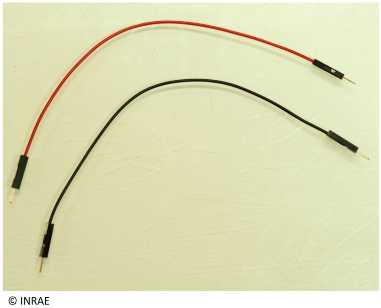
|
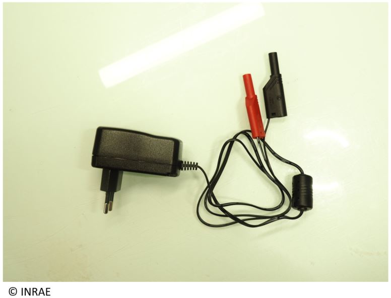
Voltcraft power supply |
1 |
|
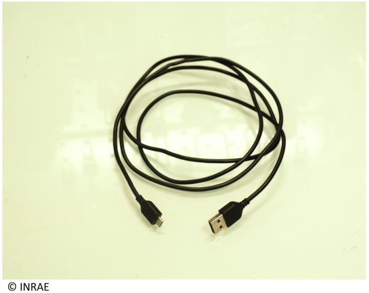
Male µ USB/male USB-A wire |
1 |
|
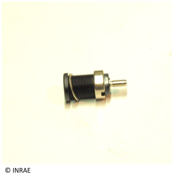
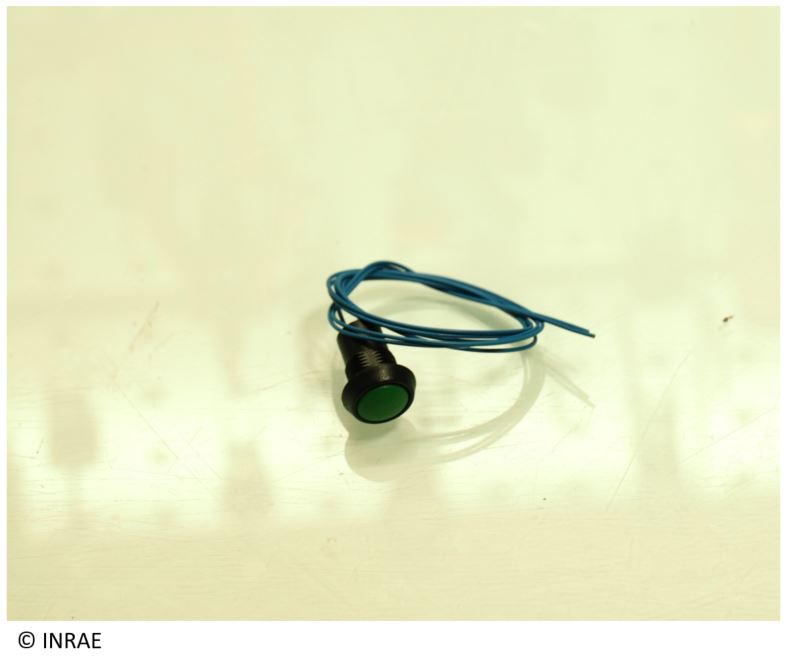
Push button (external diameter 14 mm) |
1 |
|
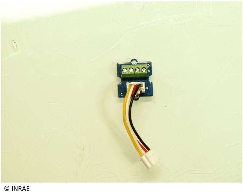
Grove screw terminal |
1 |
|
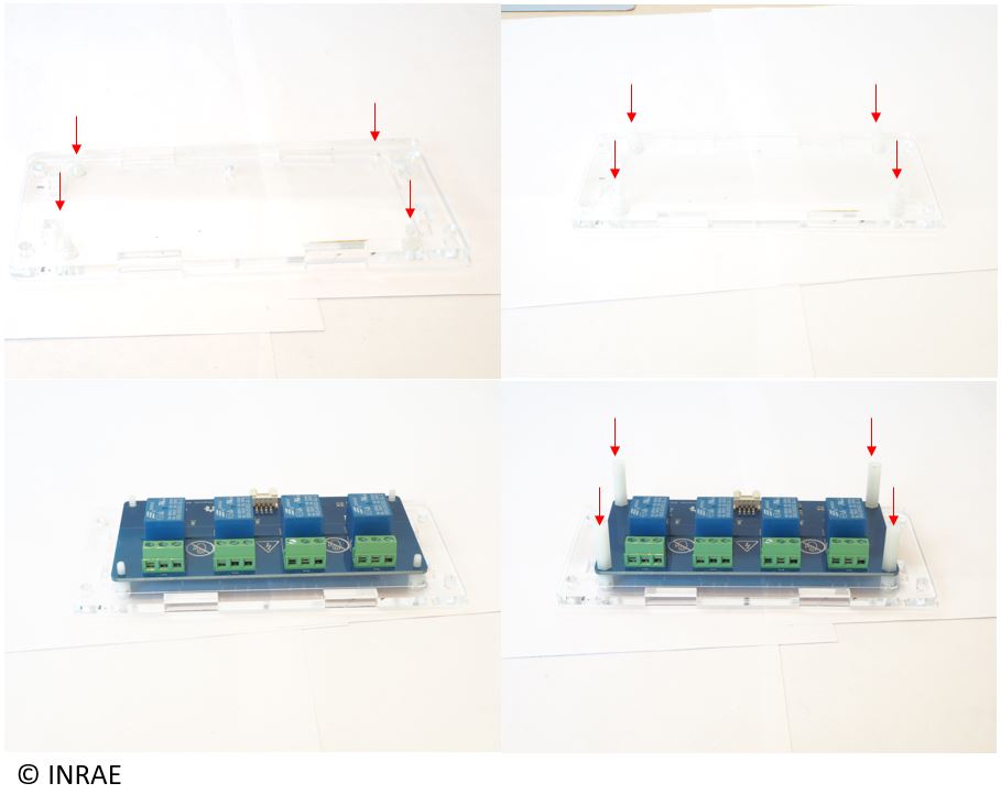
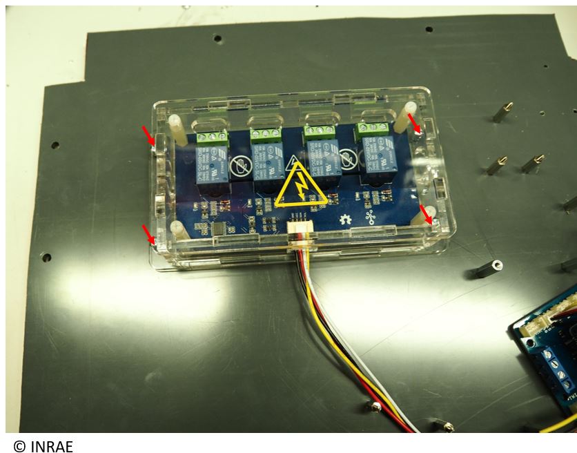
Unstick the brown scotch of the different side of protection box of the 4 relay board.
Take the electronic board of the 4 relay board and fix it on the support provided with, using screw.
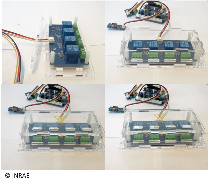
Connect the second extremity of the double wire grove on the 4 Relay board (passing through the hole of the protection box). Be careful, it’s necessary to force a little.

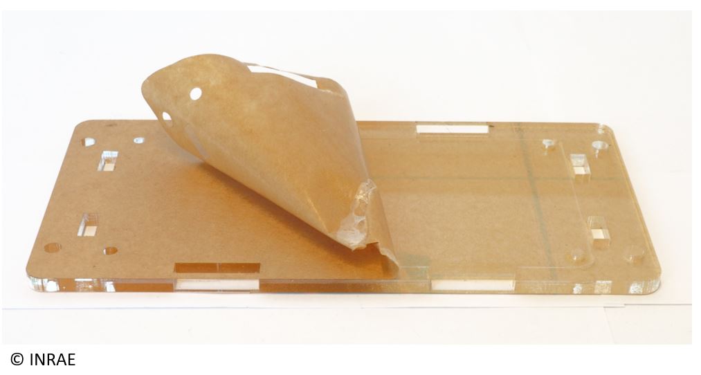
Take the 4 vertical side of the protection box, and insert it on the 4 relay board support. Then, take the top part and fix it using spacer provided with the 4 relay board.
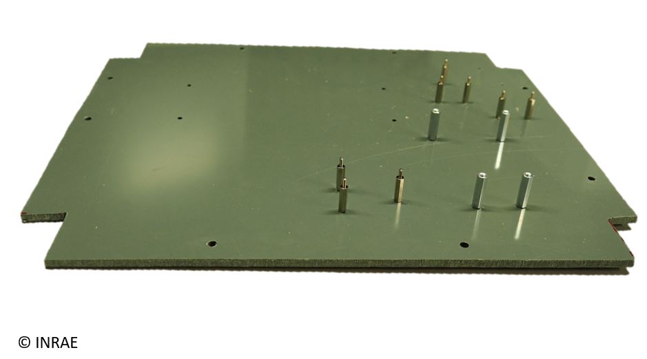
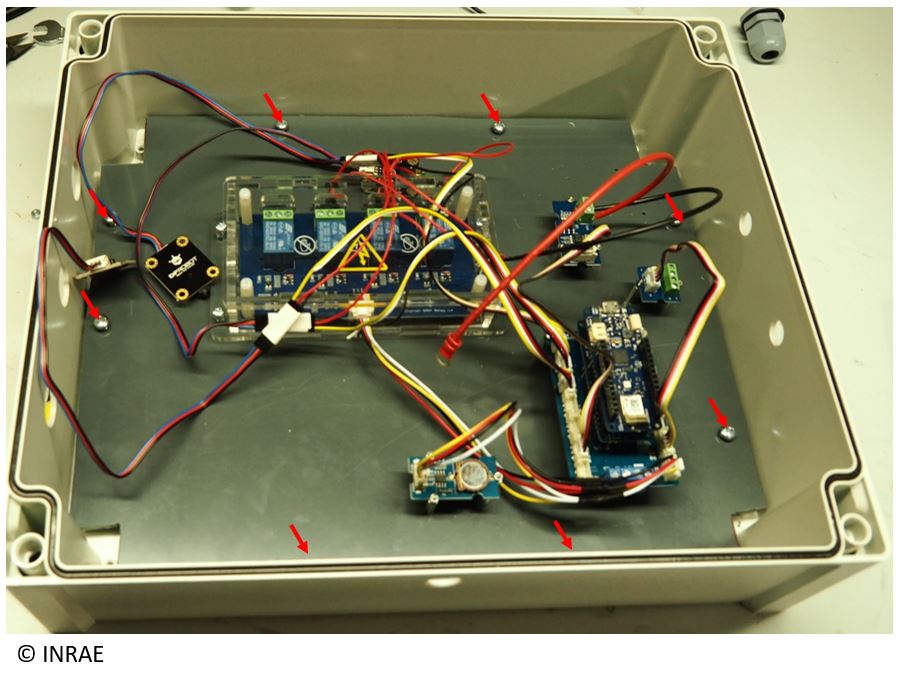
Take a piece of wood, PVC, or some other non-conductive element, and cut it following the folder “Energy_datalogger_hole.pdf” to do the fixing plate of the different datalogger board. Drill hole to put on the spacer inside it, then fix it.
Fix the protection box of the 4 Relay board on the PVC plate.
Fix the Arduino MKR Carrier on the spacer provided for that purpose, with some screw (following the folder “”Energy_datalogger_hole.pdf”).
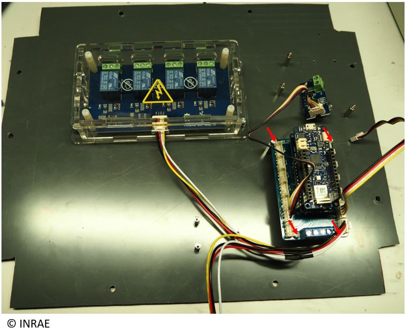
Fix the RTC module on the spacer provided for that purpose with some screw (following the folder “Energy_datalogger_hole.pdf”).
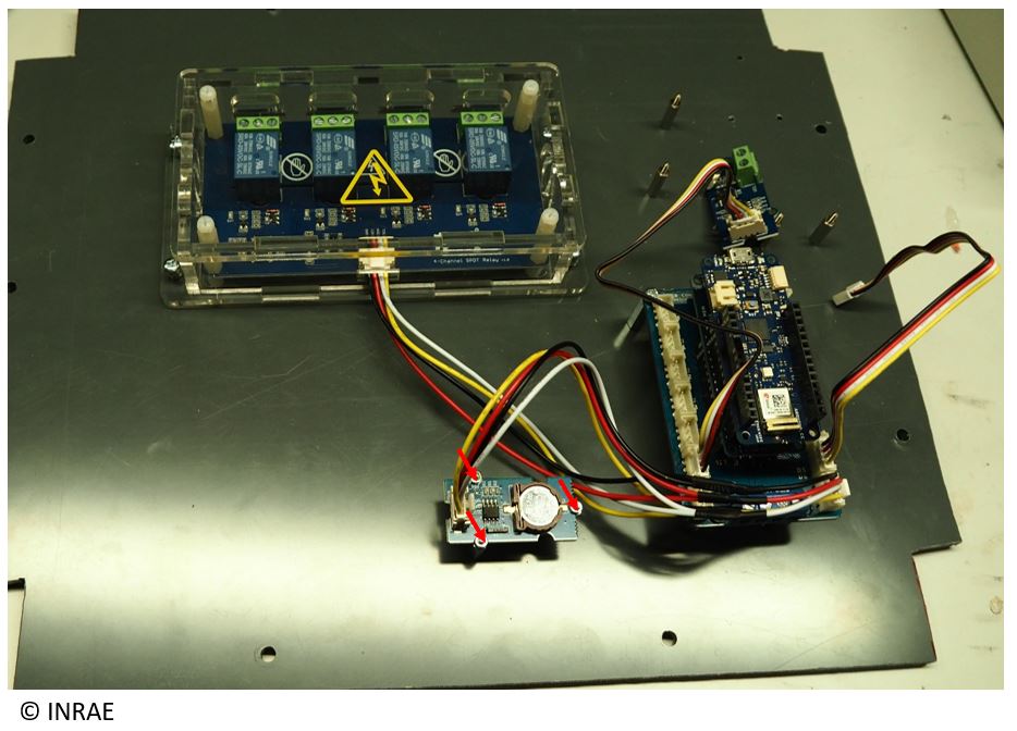
Fix the voltage divider board on the spacer provided for that purpose with some screw (follwing the folder “Energy_datalogger_hole.pdf”).

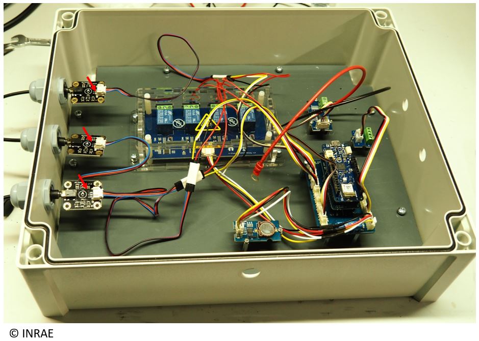
Take the electronic board of the sensor and connect its wire (provided with the sensor) on the board.

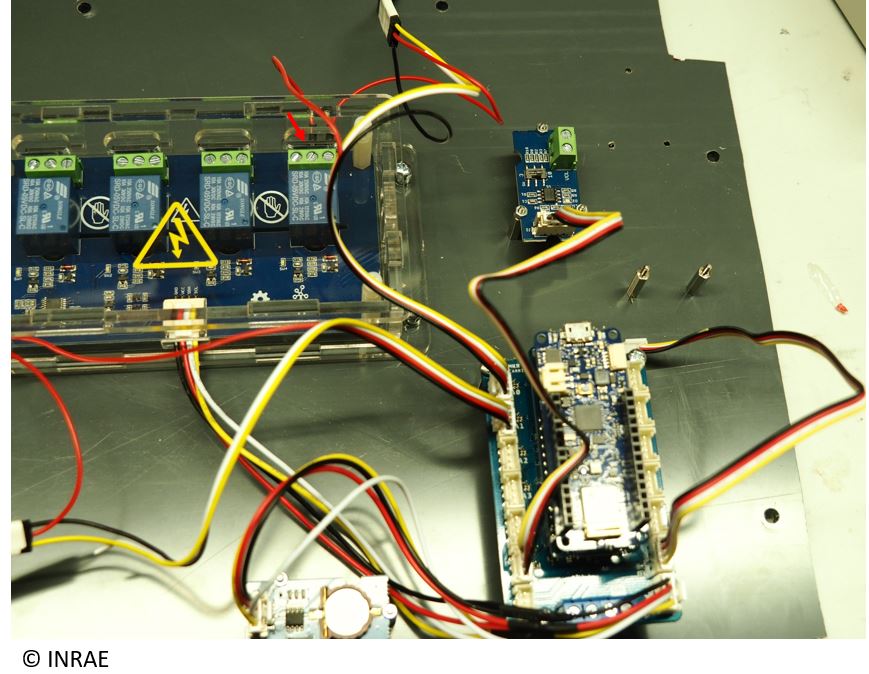
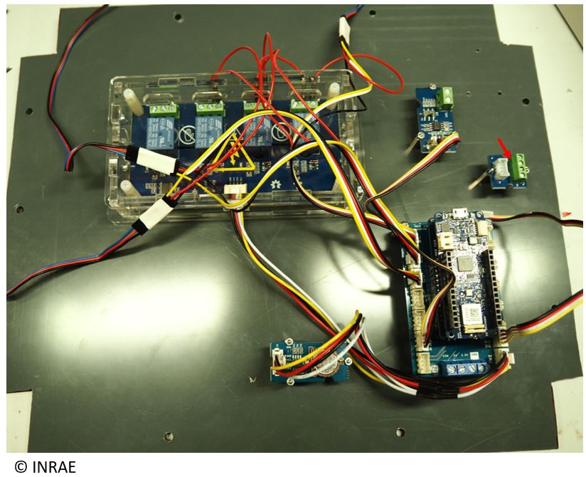
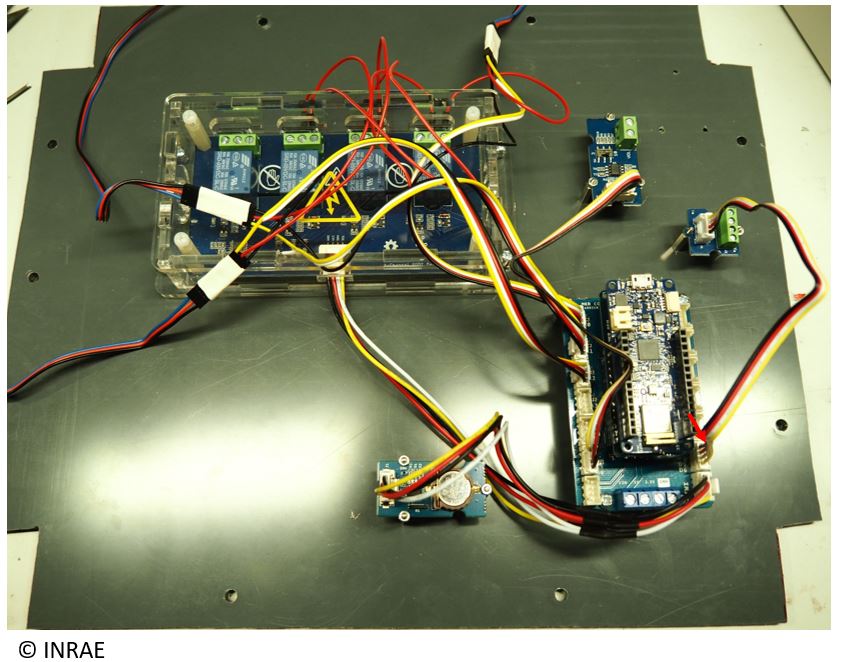
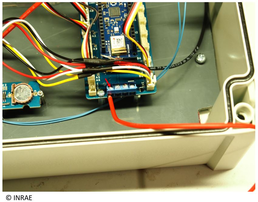
Connect the Grove/picot wire on the MKR CARRIER. On that board, the output associate to the current sensor connexion are on the A0, A1, A2 and A3 port (Here, we only use the A0, A1 and A2 port for 3 sensor connexion).
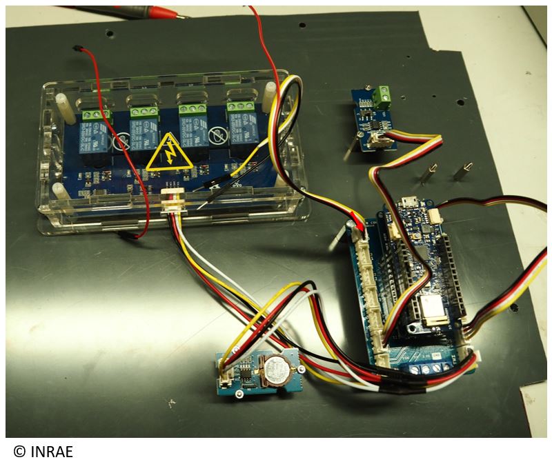
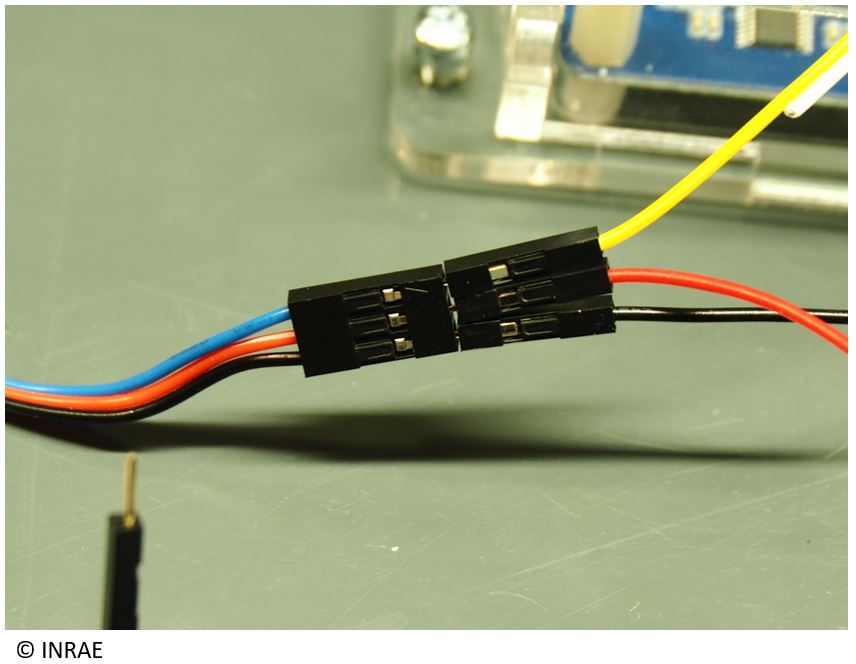
Take the black wire of this Grove/picot wire, and connect it on the triple connector of the wire coming from the sensor board (black on black).

Take the yellow wire of this Grove/picot wire, and connect it on the triple connector of the wire coming from the sensor board ( yellow on blue).
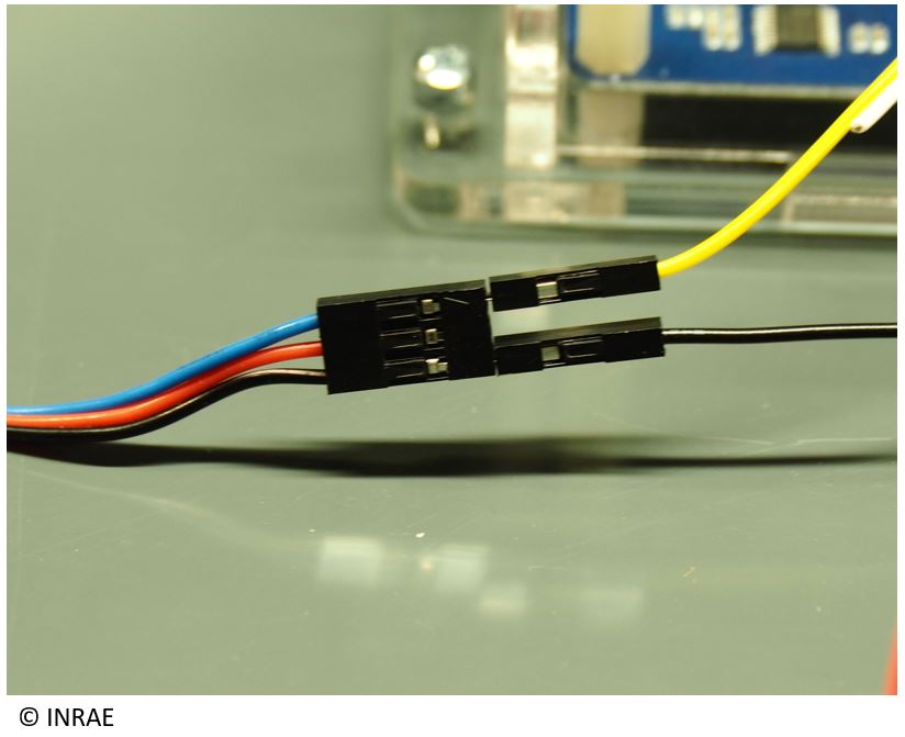
Take an independant red wire and connect one side on the triple connector of the wire coming from the sensor (red on red).
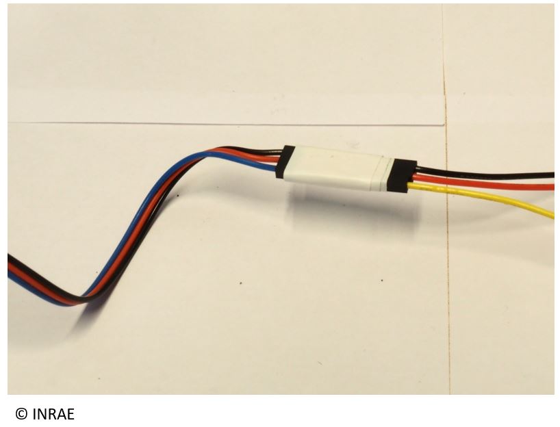
With scotch, stick together all the wire connecter to the triple wire coming from the sensor board.
Connect the red wire coming from the triple connector to the left side of the SW4 relay.
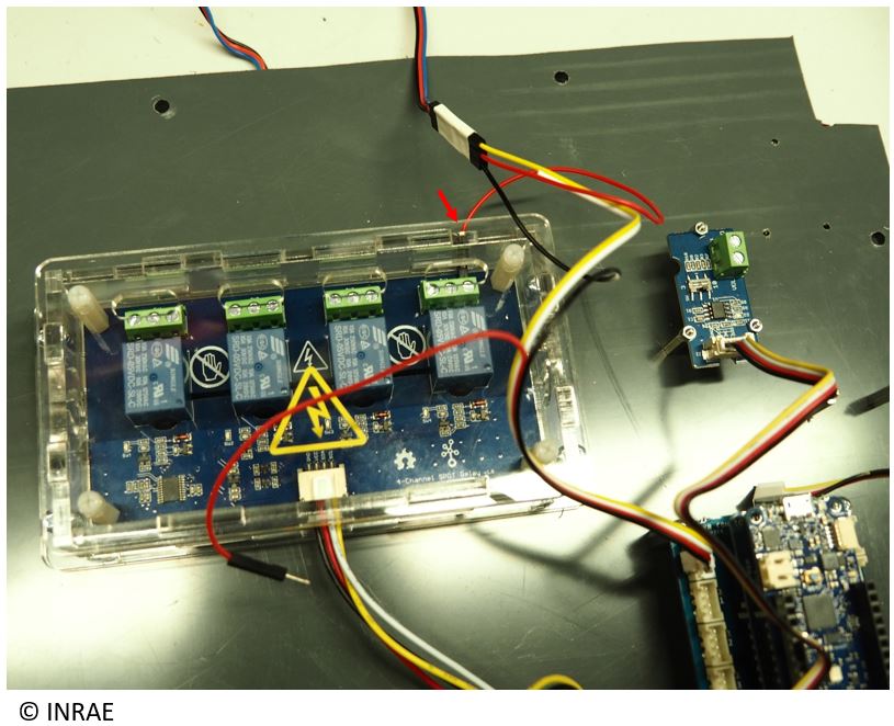
Connect the red wire coming from the A0 port on the middle part of the SW4 relay. Do step 16 and 17 for each connected sensor on that datalogger (for example, here, the SW4, SW3 et SW2 relay will be use).
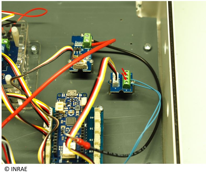
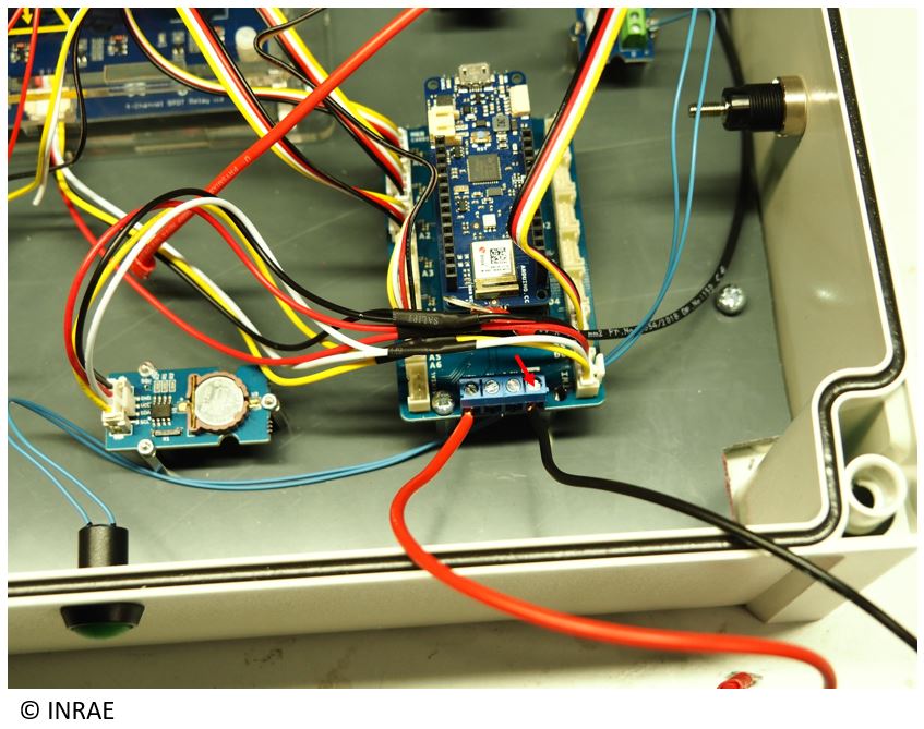
Fix the Grove screw terminal on the spacer provided for that purpose with some screw (following the folder “Energy_datalogger_hole.pdf”).
Connect the Grove screw terminal on the MKR Carrier.
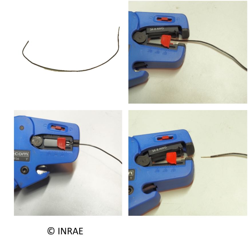
Cut 12cm of red wire diameter 3 mm. Use a wire stripper to strip 1 cm on both side of the wire.
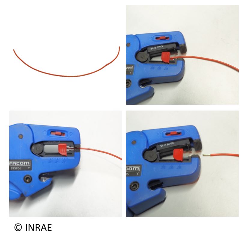
Cut 12cm of black wire diameter 3 mm. Use a wire stripper to strip 1 cm on both side of the wire.
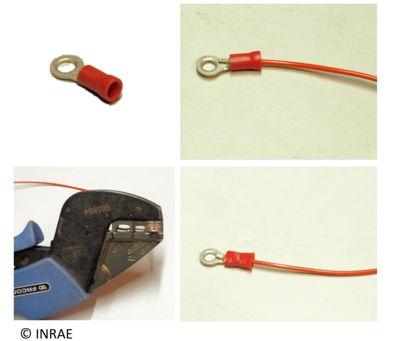
Take a crimp lug. Use a crimping tool to fix the crimp lug on one side of the red wire diameter 3 mm.
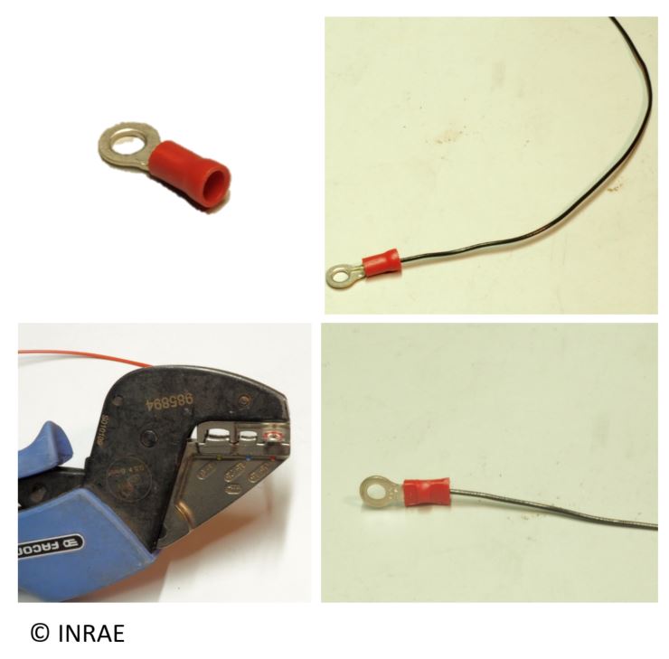
Take a crimp lug. Use a crimping tool to fix the crimp lug on one side of the black wire diameter 3 mm.
Take one of the red wire diameter 3 mm, connect one side of the wire on the GRD port of the voltage divider board. Screw it.

Take one of the “red wire diameter 3 mm”, connect one side of the wire on the VOL port of the voltage divider board. Screw it.

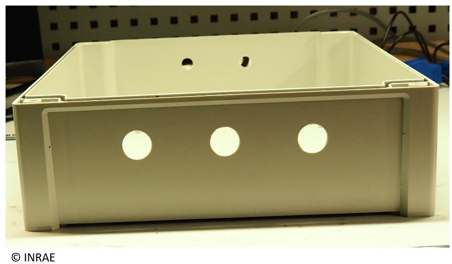
Drill a M18 hole for each sensor on one side of the box.
Put and fix the PVC plate inside the box.
Fix the cable gland on the hole that were drill before.
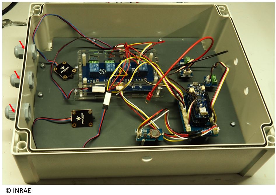
Take the current sensor (SEN0287, SEN0288 or SEN0211) and plug there jack wire inside the cable gland.
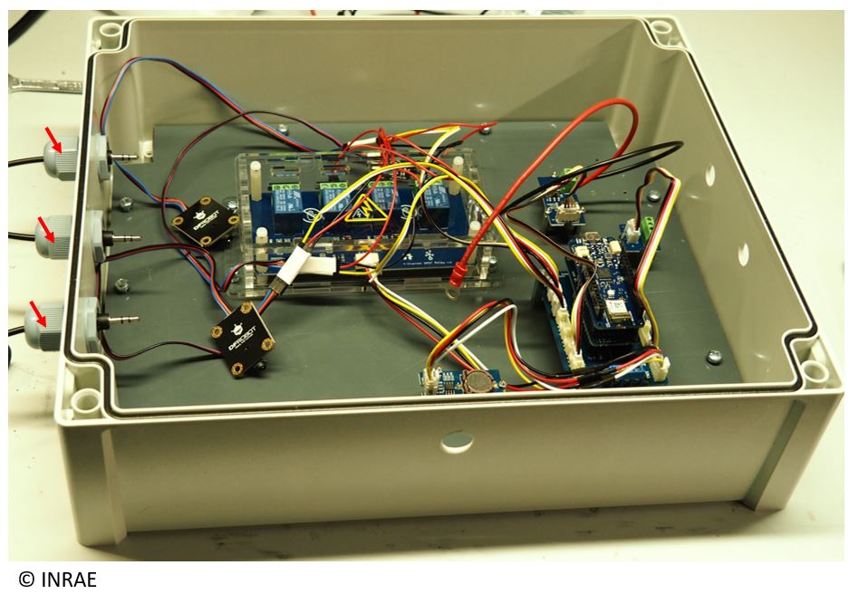
Connect the jack wire of the sensor on their electronic board.
Fix their electronic board on a PVC plate using collar.
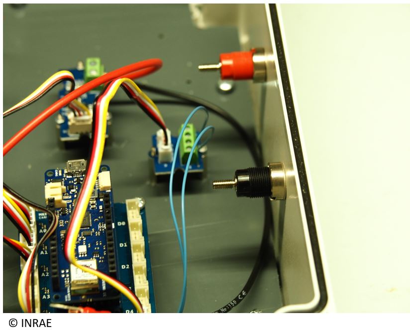
Put the push button inside its hole (hole diameter is 14 mm).
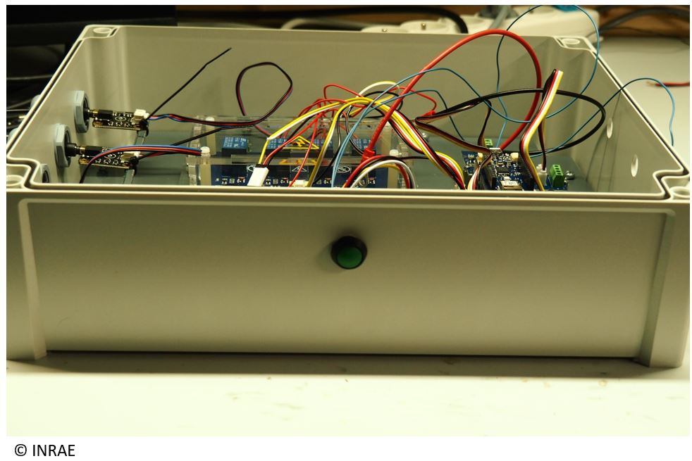
fix the push button inside his hole using a nut.

Connect both wire from the push button on the Grove screw terminal (one of the wire must be connect on the VCC port, and the other on the D2 port), then, screw it.
Take one red banana plug. Insert it inside there hole (hole diameter 12 mm), then fix it (a nuts is provided with the banana plug).

Take one black banana plug. Insert it inside there hole ((hole diameter 12 mm), then fix it (a nuts is provided with the banana plug).
Connect one side of the second red wire diameter 3 mm on the VIN port of the MKR CARRIER.
Connect one side of the second black wire diameter 3 mm on the GND port of the MKR CARRIER.
Connect on the red banana plug both red wire diameter 3 mm with the crimp lug coming from the voltage divider and the MKR CARRIER.
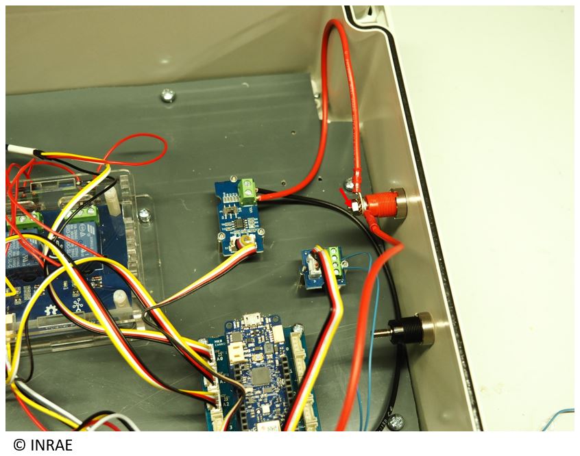
Connect on the black banana plug both black wire diameter 3 mm with the crimp lug coming from the voltage divider and the MKR CARRIER.

Close the box. The energy datalogger is ready to be use. Be careful, the datalogger need an 12V DC power supply, use an adapted power supply.